Scan from manual shows location of all switches in X-700 model.
|
Ever wondered how Minoltas X700 looks from inside ? I did too and also
was afraid to take it apart. But I got me a defective one and took the scans
below so you can see the details normally you can't. Scan from manual shows location of all switches in X-700 model. |
This show the parts of the viewfinder and the removement
of the bottom cover.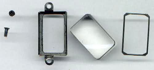 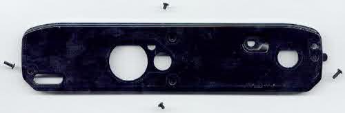
|
This shows the dials that have to be removed before removing
the top cover. 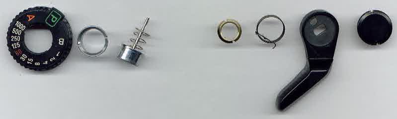 |
Takeing off the top cover with three screws. One small button
falls out. The wires to piezo buzzer and flash socket. Major repairs in upper electronic section require it almost to remove the wires as they will otherwise come off easily. 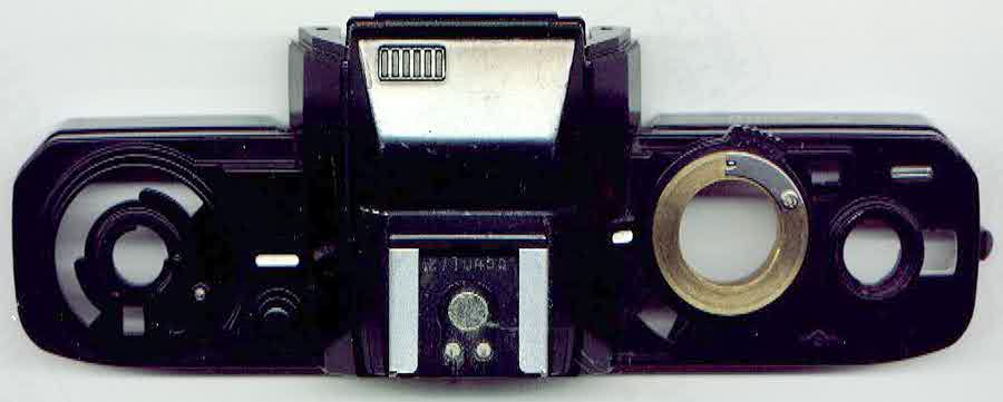 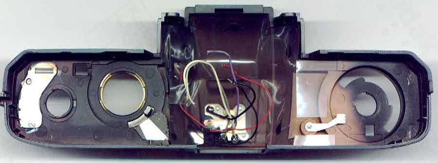 |
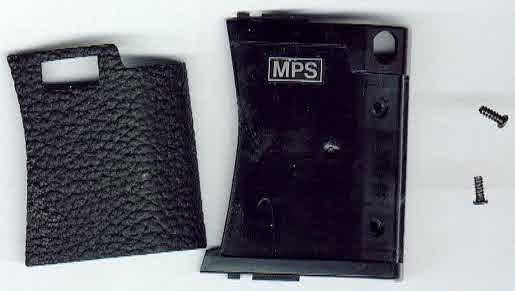
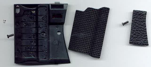
The back door ist easily removed. Just push the small lever
a little bit aside and the door comes off.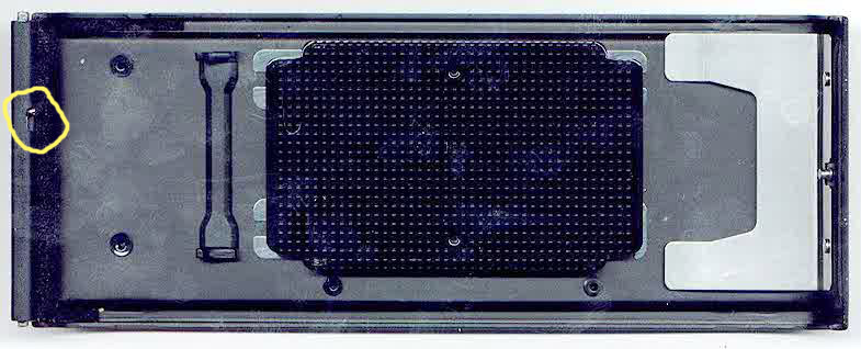 |
|
Before removing the circular plastic
ring, you have to remove the parts and screws in this and the next picture.
 |
 |
This plastic ring is fixed with
two tiny screws. After removal the button for lens release and DOF preview
falls off. |
This variable resistor ring is definitively
broken. It transmits the aperture set to the meter and also the setting
of the "P" lever for MD lenses. Check this part and/or wires if meter is constantly showing over-/underrange in viewfinder 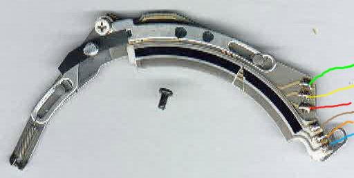 |
|
The metal baseplate with tripod connection and battery compartment.
  |
||||
Main flexible PCB top view with colored wires as seen in
original assembly.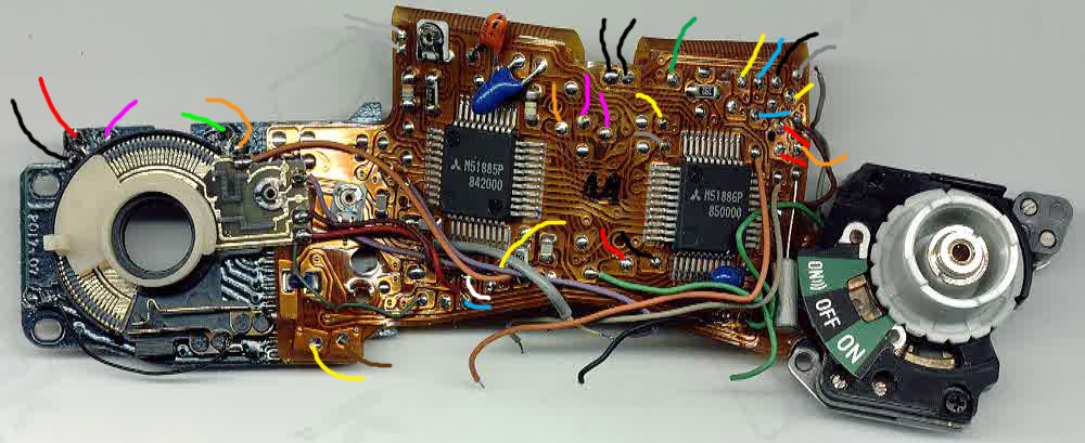 |
Main PCB bottom view. See the black/leftmost capacitor which
also fails frequently. 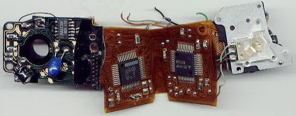 |
Main PCB unfolded.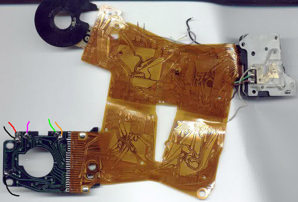 |
Main PCB unfolded parts side with four ICs. |
|
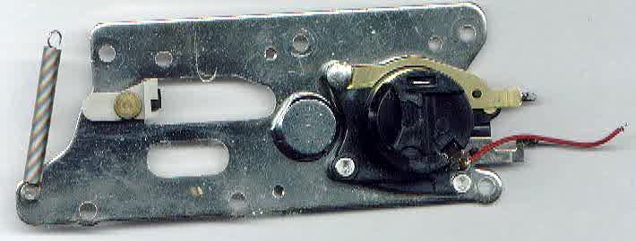
Chassis part with wires from base plate and winding mechanism.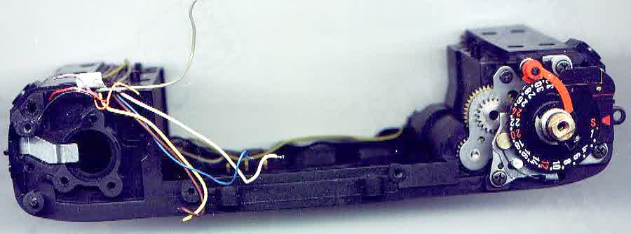 |
Back view.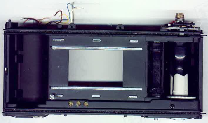 |
Chassis view from bottom with PCB holding capacitor (fails
frequently) and winding gears. 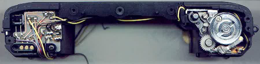 |
Chassis front view with wires from bottom to top.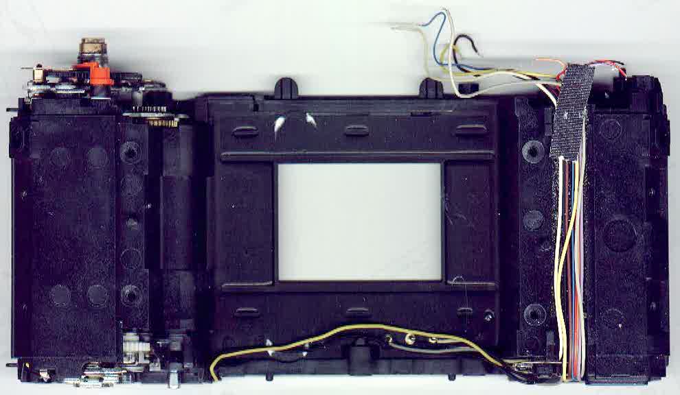 |
|
Shutter block view from film side.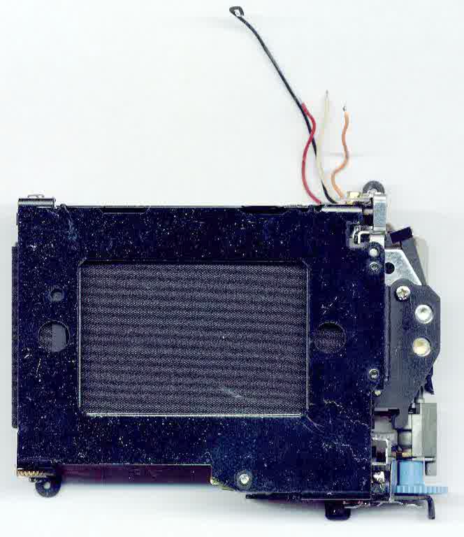 |
Shutter block from lens side. Wires to central PCB.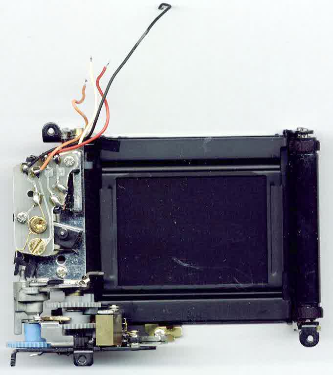 |
|||
Mirror box from front. |
Mirror box from rear.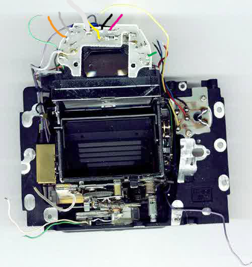 |
Mirror box top view / pentaprism.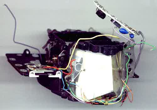 |
Mirrorbox bottom view with release magnet. |
|